Motherboard Fan connectors
The motherboard has specific pinouts for various fan connectors, such as the CPU fan, System fan, and Case fan connectors.
The motherboard has specific pinouts for various fan connectors, such as the CPU fan, System fan, and Case fan connectors. Below are the pinouts for each type:
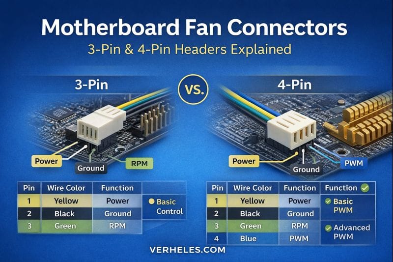
1. CPU Fan Connector (4-Pin or 3-Pin)
The CPU fan header is typically a 4-pin or 3-pin connector, with the 4-pin version allowing for more advanced speed control (PWM).
4-Pin CPU Fan Pinout:
| Pin | Function |
|---|---|
| 1 | Ground (GND) |
| 2 | Power (12V) |
| 3 | Tachometer (Fan Speed) |
| 4 | PWM (Pulse Width Modulation, for speed control) |
3-Pin CPU Fan Pinout:
| Pin | Function |
|---|---|
| 1 | Ground (GND) |
| 2 | Power (12V) |
| 3 | Tachometer (Fan Speed) |
2. System Fan (SYS FAN) or Case Fan Connector (3-Pin or 4 Pin)
Similar to the CPU fan header, system or case fan headers can either be 3-pin or 4-pin connectors.
4-Pin System Fan Pinout:
| Pin | Function |
|---|---|
| 1 | Ground (GND) |
| 2 | Power (12V) |
| 3 | Tachometer (Fan Speed) |
| 4 | PWM (Pulse Width Modulation, for speed control) |
3-Pin System Fan Pinout:
| Pin | Function |
|---|---|
| 1 | Ground (GND) |
| 2 | Power (12V) |
| 3 | Tachometer (Fan Speed) |
Key Notes:
- The 3-pin fans are controlled based on voltage (i.e., their speed depends on the voltage provided), whereas the 4-pin PWM fans are controlled via a signal to modulate fan speed.
- The tachometer pin (usually pin 3) provides the fan speed signal, which the motherboard uses to monitor and adjust the fan speed.
- Some modern motherboards feature fan headers that automatically detect whether you’ve plugged in a 3-pin or 4-pin fan, adjusting control accordingly.
This pinout is common across most motherboards, though it’s always a good idea to consult your motherboard manual for the exact pinout, as it may vary slightly between different models.


Comments ()